

When a device fails EMC testing, it can suddenly delay product launches and increase costs due to redesigns and retesting.
Understanding and mitigating emissions are essential to creating reliable, compliant electronics. In this blog post, we will introduce the two primary types of emissions and offer practical steps for troubleshooting both conducted and radiated EMC issues.
Understanding Conducted vs. Radiated Emissions
EMC emissions are broadly categorized into two types: conducted and radiated. Conducted emissions are noise currents traveling out of the product back onto the AC mains cable. These emissions can interfere with other equipment connected to the same power source. Typically, the frequencies of concern for this noise range from 150 kHz to 30 MHz. Radiated emissions, on the other hand, are electromagnetic fields that radiate through the air from the product and can interfere with nearby electronics. Typically, the frequencies of concern for this noise range from 30 to 6000 MHz.
Troubleshooting Conducted Emissions
When addressing conducted emissions, the first step is identifying the source within the device. Common culprits include switching power supplies, motor drivers, and high-speed digital circuits. Using a Line Impedance Stabilization Network (LISN) in conjunction with a spectrum analyzer can help isolate the frequency bands causing failures.
Once the frequencies are identified, the next step is to locate the physical origin. A current probe can be used to measure emissions on individual cables to pinpoint noisy lines. Mitigation often involves improving PCB layout—such as minimizing loop areas and ensuring solid return paths—and implementing filtering techniques. Installing differential-mode and common-mode filters at power entry points can significantly reduce emissions. In some cases, re-routing cables or adding ferrite beads may also help.
Troubleshooting Radiated Emissions
Radiated emissions are often more challenging to troubleshoot. Initial testing is typically performed on the complete device under test (DUT) to verify compliance with emissions standards.
If the DUT fails, diagnostic tools such as near-field probes paired with a spectrum analyzer become invaluable for identifying hot spots on the PCB. Focus should be placed on areas with high-speed digital signals, clock lines, and power converters, as these are frequent sources of unwanted radiation.
Shielding is a common solution, but it should be a last resort after addressing fundamental design issues. Improving grounding and ensuring low-impedance paths can reduce emissions at the source. Additionally, managing cable routing to prevent unintentional antennas and using properly terminated signal lines can reduce unwanted radiation. Antenna-like structures, such as long traces or unterminated cables, should be minimized or shielded effectively.
Digital clocks are often a major source of high-frequency radiated emissions; techniques such as improving clock distribution and using spread spectrum clocking can help mitigate these emissions.
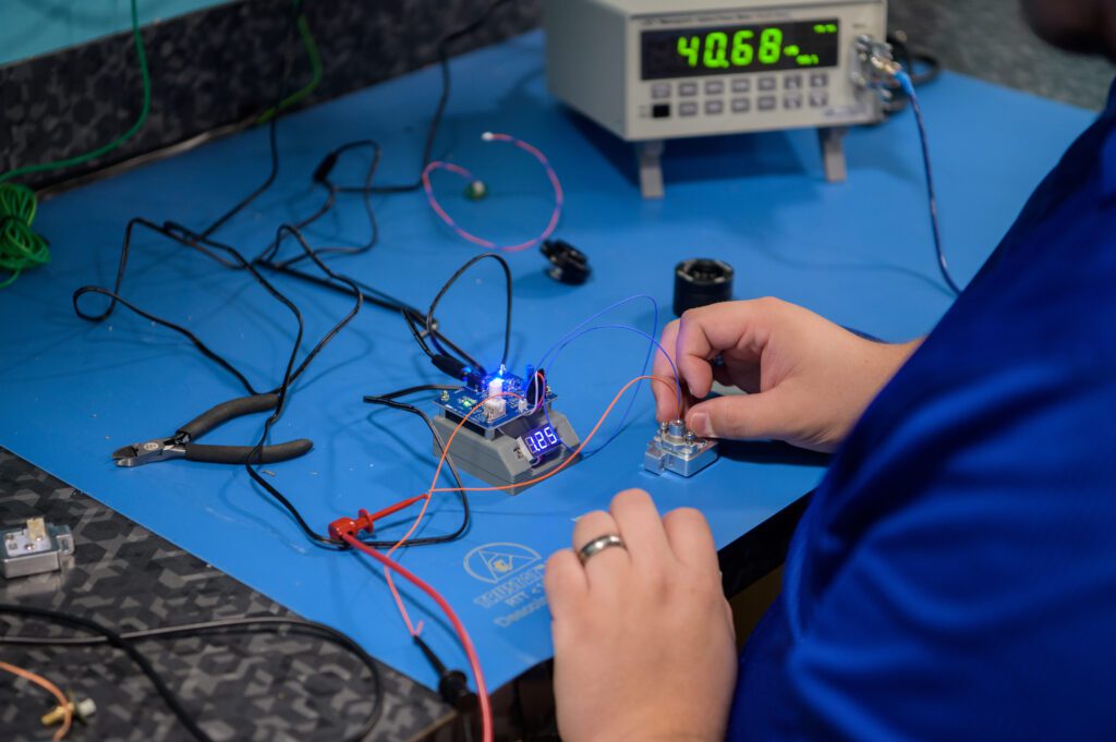
An engineer at Gilero works with electronics at a test bench
How to Catch Issues Early
By systematically approaching conducted and radiated emissions—starting with measurement, followed by localization and mitigation—a skilled engineer an resolve EMC issues efficiently.
Catching EMC issues early in the design process is key to ensuring both compliance and product reliability. Start by integrating EMC requirements into the design brief, considering relevant standards and potential interference sources. Early use of electromagnetic simulation tools can help predict how your product will behave in its electromagnetic environment, allowing you to adjust designs before physical prototypes are made.
After developing the first prototype, you should perform pre-compliance EMC testing to measure both radiated and conducted emissions. This helps identify major issues early on. Near-field scanning can then pinpoint high-frequency emission sources, allowing for targeted design modifications. Basic mitigation techniques like decoupling capacitors, shielding, and grounding can be applied to prototypes to address issues immediately.
Now, iterative testing is essential… you need to retest with each design revision to ensure that these mitigation strategies work. Use tools like spectrum analyzers and oscilloscopes for real-time feedback. Before finalizing the design, schedule pre-compliance testing at a specialized facility to catch any remaining issues.
Then, once the product is finished, we’ll conduct system-level EMI/EMC certification testing to verify that it does not interfere with other devices in the final product.
For a comprehensive, hands-on guide to EMC troubleshooting, including detailed procedures, equipment setup, and results analysis, I recommend Workbench Troubleshooting EMC Emissions (Volume 2) by Kenneth Wyatt. Drawing on over 30 years of experience at Hewlett-Packard and Agilent Technologies, Wyatt provides clear explanations, real-world examples, and expert tips that are especially valuable for engineers working in design and compliance testing.
Bring Your Project to Gilero
If you’re in need of expert assistance in developing or manufacturing medical devices, drug delivery systems, or combination products, Gilero is a trusted engineering and manufacturing partner for innovators in the MedTech industry. We help innovators in MedTech bring safe, reliable devices to market by developing and testing products to rigorous medical device standards like IEC 60601. From electrical safety and EMC testing to mechanical, thermal, and performance verification, our team ensures your devices meet regulatory requirements and perform as intended.
To minimize risks and reduce costly delays, we rigorously test products in the early stages of development. We identify and address potential EMC-related issues before they become problems. This proactive approach ensures your product complies with regulatory standards and performs optimally.
With our expertise, you can confidently navigate the challenges of product development and bring your innovations to market. Trust us with your next complex electromechanical project.
